Sunday, June 23, 2013

Refractometer Brewing Charts

A refractometer is an instrument used by brewers to infer the sugar content/alcohol content of wort and beer. It produces similar results to that of a hydrometer, but rather than requiring approximately 100 mL of liquid, it only takes a number of drops.  Unfortunately, a refractometer is sensitive to alcohol content, so a correction must be made in order to compare the readings from these two instruments.

I've put together a group of Matlab files that calculate these corrections and plot a number of useful graphs. It's available on the Matlab file exchange here. This is based on beerlib.c, by Domenick Venezia.


Edit: here's an additional chart in case your refractometer reads in SG units and you want to correct for alcohol content:

Friday, September 28, 2012

Geodesic Airolite Classic 14 Part 2


Here's the second part of my series on the build of a Geodesic Airolite boat, a Classic 14 sailing/rowing dinghy. The last entry detailed the majority of the woodwork; this one shows adding the synthetic materials as well as some odds and ends.

Where we left off last posting: here's a photo of the frame with foils (daggerboard and rudder) installed to show their proportions.


The next step was to install the kevlar.  This is a stiff yarn applied on the diagonals to prevent racking when the hull is put under torsional stress.


After the kevlar is attached to the frame, the polyester skin is draped loosely:


A slit is cut in the fabric at the bow and then attached with heat-activated adhesive.

The fabric is attached along the gunwale and transom and tightened by shrinking it with an iron:


Rub rails installed:


Seats were formed with scraps of skin fabric.


Here are some pics of the finished hull:


I made oars following Jim Michalak's plans. These incredibly material-efficient plans allow for a seven foot oar to be made from an eight foot 1x6 with very little waste.  The rough shape is first cut:


The two pieces cut off the sides are laminated to the center part to beef up the shaft:


The shape is then formed with a spokeshave:


Heading for a nearby surburban pond/lake/storm catchment basin:


The maiden voyage:

No leaks!


Seems much better balanced with one than with two:


Hopefully I'll have an update in the spring with sailing rig pics.

Monday, July 16, 2012

Geodesic Airolite Classic 14 Part 1

Once again I have to apologize for neglecting this blog. In any case, here's an interim post about the boat I'm working on: a Geodesic Airolite Classic 14.

The Geodesic Airolite line of boats were designed by the late Platt Monfortt, based upon observation of airplane construction methods. The distinguishing features are a very light wooden frame, a heat-shrunk dacron skin and diagonal kevlar roving. These combine to produce an incredibly lightweight and aesthetically pleasing boat what is surprisingly robust. For plans and a list of their boats, see the company's website here.

A few years ago I built a Snowshoe 14 canoe from a Geodesic Airolite kit and it turned out wonderfully. Pics here. I wanted a sailboat that I could cartop and launch single-handedly and the Classic 14 appears to fit the bill. It is modelled on a New York Whitehall boat and the specs list the weight at 54 lb for a 14 foot long boat with a 48.5 inch beam.

The first step is to cut out and mount stations to act as forms for the construction. You can see my airolite canoe hanging from the ceiling.


The longitudinal stringers are ripped from structural lumber and clamped to the stations. The clamps shown are made from slices of ABS pipe.


The notches for the stringers in the transom are cut to fit due to the compound angle. The stringers are left oversize to be cut to length after the epoxy dries. This is much easier than the double-ended canoe which required compound cuts to fit each stringer exactly to length.


The ribs are next installed. These are steamed to help bend them to shape.


The steaming rig I used is just 2" ABS pipe connected to a coffee can with some aluminum foil and heated with a hotplate. Others suggest a more complex setup with insulation, etc, but this worked fine.


I had a failure on the connection between gunwale and transom, so I beefed it up a bit, which required a bit more complicated clamping than usual.


Here's a shot of the boat just after it came off the stations. This is where I broke the transom-gunwale joint as it wasn't strong enough to carry around without the inwales and seats installed. Note the daggerboard slot.


Here's a detail showing the inwales and the construction of the seats which also help support the daggerboard well


Frame faired and sealed. Next step is applying kevlar.


Since this is a sailboat, there are a couple items to make in addition to the hull. Here's a pic of laminating two pieces of cedar to make the boom:


A sailboat also requires two foils: a daggerboard to resist sideways motion and a rudder to control direction. I made mine out of laminated plywood with an elipsical leading edge. This photo shows initial shaping of the leading edge. I did rough shaping with a power plane, followed by hand plane and sandpaper.


Filling some voids after shaping the trailing edge.


I covered the daggerboard with one layer of unidirectional fiberglass. But not before dropping the epoxy-coated board in a pile of shavings.

Monday, September 20, 2010

Console Record Player Retrofit

I apologize for the long gap between posts; most of my work has been proprietary recently, so there's not too much to share on the blog.

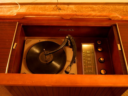
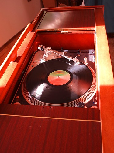
Therefore, I'm presenting a personal project: a retrofit of a late-1960s era cabinet record player. It's a Fleetwood model 4057, made in Montreal, serial 283. It came complete with AM and shortwave radio, record player and tape input, powered by a tube amp rated for 117 V, 0.95 A at the input. I believe these units were retailed by Sears. The guts were all removed and replaced by a modern turntable, digital music player, amplifier and controller.

Cabinet

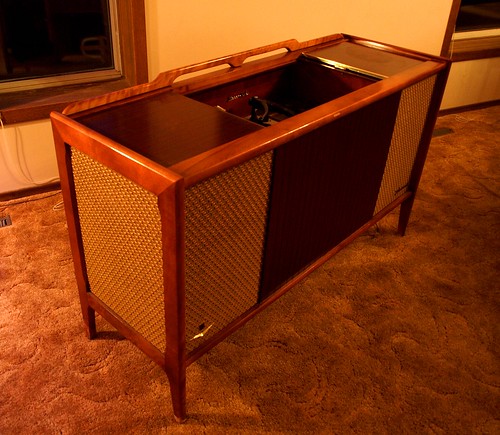
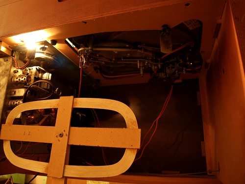
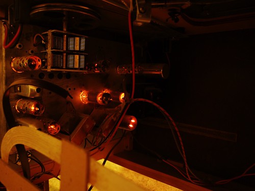
Before the retrofit, the unit lights and tubes lit up. On radio, it crackled when you adjusted the volume but couldn't be tuned to any station. The record player wouldn't rotate and no sound was produced when the record was turned by hand. So the radio/amp was removed and sent to the tube amp hospital and the record player went to the morgue.

Tube Amp and Turntable Guts

Tube Amp

Turntable and Radio

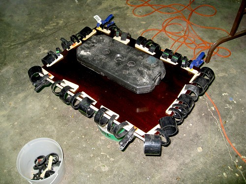
The first step in the retrofit was to replace the record player shelf as it had a large cutout for the sunken turntable. I took this opportunity to add some vibration isolation. I expected structural feedback to be a significant problem because the speakers and turntable are mounted in the same unit, as opposed to satellite speakers. Thus, the turntable shelf was designed to be a massive vibration isolator. The shelf is constructed of a wood frame with hardboard top and bottom panels, filled with sand.

Isolation Platform

Isolation Platform

The turntable was replaced with a Stanton T.80 turntable, capable of digital S/PDIF output.

Turntable

Next: digital music. Digital music is played by a VIA Epia M10000 mainboard. This is a small form-factor (Mini-ITX) low-power computer. It's a bit underpowered for video, but is perfect for a mp3 and internet radio player. I've installed Ubuntu server and use VLC as a media player, controlled either over SSH or with its web interface.

Amplifier

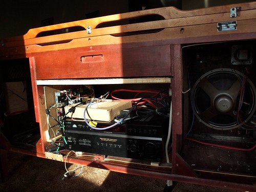
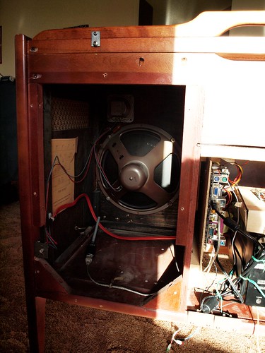
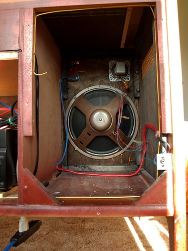
The amplifier is an older Sony, purchased second hand for cheap. It sits in the centre cabinet. The computer provides one analog input and the turntable provides a digital input. The integrated speakers mean that the speaker cables need not be flexible after installation, so I used solid 12-gauge residential electrical cable ($1/foot at Rona for essentially no resistance and no chance of phase distortion from complex impedance). The original speakers (12-inch woofer and tweeter) haven't been replaced yet (and may not be).

Left Speaker

Right Speaker

Since the amp is mounted in the belly of the cabinet, the remote no longer works. I worked around this by using a microcontroller to relay the IR remote signals. There is an IR sensor behind the cloth of the right speaker, which is processed by an ATMEGA168 microcontroller. Signals destined for the amplifier (Master Volume, etc) are repeated on an IR LED temporarily taped to the amplifer's remote input. Signals that target the digital music player (track forward, etc) will be passed to the computer over USB (this functionality is not done yet). The USB link will also allow one to control the amplifier over the network. A preamp and mixer will use digital pots driven by the microcontroller to adjust the relative levels and tone of the turntable, digital music player and an aux input. This function is not yet operational, but I can dim three leds using the remote. All of this is being prototyped on an Arduino board since it has USB connectivity and there is a nice library of IR remote functions (written by Ken Shirriff).

Fake remote

So how does it sound? I haven't done any acoustic analysis yet and I hate audiophile-style subjective reviews, but, to my ears, it sounds really good, especially considering the vintage speakers. There is no discernible distortion at normal listening levels (as long as I remember to set the soundcard gains to avoid digital clipping).

Unfortunately, my massive sound isolator is not super effective. At high gains there is a 94.1 Hz feedback that can be eliminated if I put all my weight on the cabinet. This frequency corresponds to a 10.6 ms delay (assuming there is no signal phase changes) which at a sonic speed through wood of 3300 m/s would require a signal path of 35 m, clearly much longer than the size of the console. This leads me to believe there is a significant delay in the turntable's analog to digital conversion process. Perhaps switching to the analog output (with presumably no delay) will solve this problem, although it may just move it to a higher frequency. Alternately, the solution may be to reduce the coupling between the cabinet and the turntable shelf. The shelf is a relatively tight fit so the effective spring between the console and the shelf is relatively stiff. I plan to modify the shelf mounting so that it has no solid contact with the cabinet, being suspended on acoustic foam or a semi-liquid like acoustic caulk or Blutack.


Next: performance characterization and speaker optimization.

Edit 20/09/2009: I almost forgot to mention that I plan to host a session on microcontrollers at Bar Camp Saskatoon.